Description
Parameters
| Features | Applications |
| Up to 128 channels | Ring network |
| Low insertion loss | Remote monitoring in optical network |
| Parallel interface | Testing of fiber optical component |
| Modularized design | |
| Epoxy free on optical path |
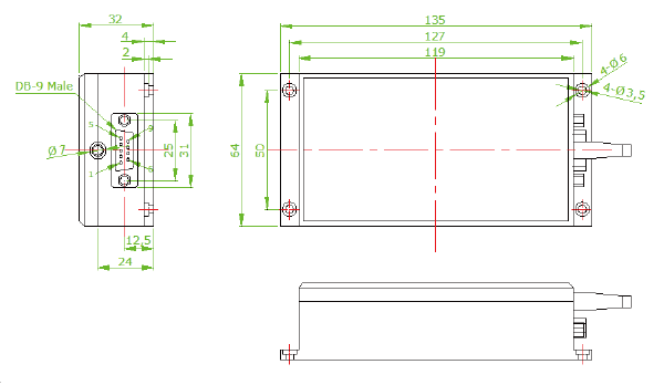
Mechanical Dimensions
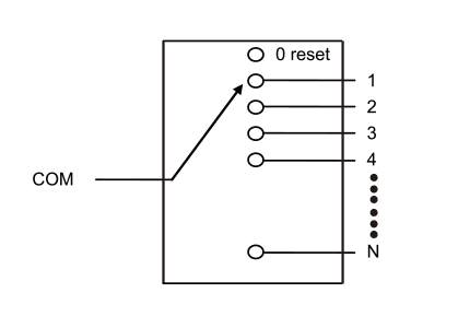
| Optical Route | Example:135×64×32mm(n≤12,DB-9 male) |
 |  |


| Parameter | FY-1XN | |||
| Insertion Loss(dB) | 1<N≤12 | 16<N≤32 | 32<N≤64 | 64<N≤128 |
| Type:0.8 Max:1.0 | Type:0.8 Max:1.0 | Type:1.2 Max:1.5 | Type:1.7 Max:2.0 | |
| Wavelength Range(nm) | 850nm,1260~1620nm | |||
| Operating Wavelength(nm) | 850/1310/1550/1625 | |||
| WaveLength Dependent Loss(dB) | ≤0.25 | |||
| Channel Crosstalk(dB) | MM≥35 SM≥55 | |||
| Return Loss(dB) | MM≥30 SM≥50 | |||
| Polarization Dependent Loss(dB) | ≤0.05 | |||
| WaveLength Dependent Loss(dB) | ≤0.25 | |||
| Temperature Dependent Loss(dB) | ≤0.25 | |||
| Repeatability(dB) | ≤±0.05 | |||
| Power Supply(V) | 5.0 or 12.0 | |||
| Lifetime(time) | ≥10^7 | |||
| Switch Time(ms) | ≤8 | |||
| Transmission Power(mW) | ≤500 | |||
| Operating Temperature(℃) | -20~+70 | |||
| Storage Temperature(℃) | -40~+85 | |||
| Dimension(mm) | 1<N≤12(135×64×32) | 12<N≤16(184×78×36) | 16<N≤32(140×77.5×64) | 31<N≤88(184×156×66) |
| 88<N≤128(184×220×66) | &nsbp; | &nsbp; | &nsbp; | |
1、Specifications may change without notice.
2、Above specification are for device without connector.
| Pin No. | signal Name | I/O | Description |
| 1 | D0 | Input | TTL,Channel selection bit 0 |
| 2 | D1 | Input | TTL,Channel selection bit 1 |
| 3 | D2 | Input | TTL,Channel selection bit 2 |
| 4 | D3 | Input | TTL,Channel selection bit 3 |
| 5 | /RESET | Input | TTL,Low level reset to channel 0.Highh leve means channel selection bits are effective. |
| 6 | /READY | Onput | TTL,Ready(High=Not ready,Low=Ready). |
| 7 | ERROR | Onput | TTL,Error(High=Error,Low=Not error). |
| 8 | GND | Input | Ground |
| 9 | +5VDC | Input | 5.0±5% VDC Power Supply(max 550mA) |
| Max Channel | Input | Active Channel | |||||||
| /RESET | D6 | D5 | D4 | D3 | D2 | D1 | D0 | ||
| N=16 | 0 | x | x | x | x | x | x | x | 0 reset |
| 1 | x | x | x | 0 | 0 | 0 | 0 | com → 1 | |
| x | x | x | 0 | 0 | 0 | 1 | com → 2 | ||
| x | x | x | 0 | 0 | 1 | 0 | com → 3 | ||
| x | x | x | ··· | ··· | ··· | ··· | ··· | ||
| x | x | x | 1 | 1 | 1 | 1 | com → 16 | ||

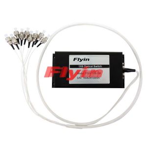
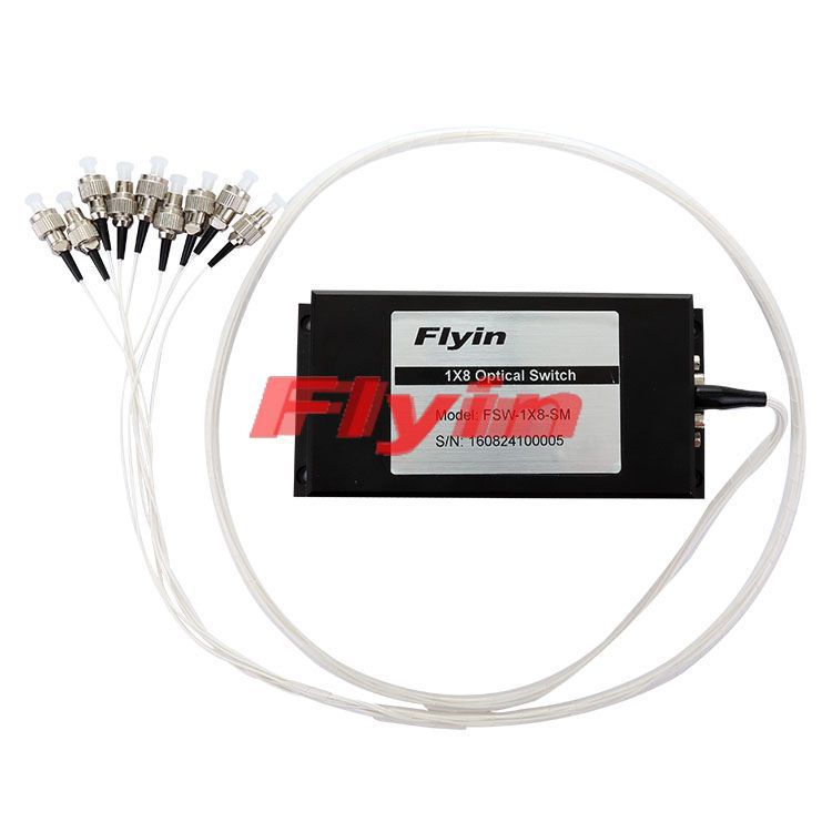
Flyin Optronics’ 1xN Mechanical Fiber Optic Switch connects optical channels by redirecting an incoming optical signal into a selected output fiber. This is achieved using a patent pending opto-mechanical configuration and activated via an electrical control signal. The mechanical operation offers ultra-high reliability and fast switching speed as well as bi-directional performance. The MMS fiberoptic switches are true switching solutions for optical networking applications.
| Channel: |
1~128custom |
| Mode: |
SM MM |
| Voltage Type: |
3V 5V |
| Control Model: |
Latching Non-Latching |
| Fiber Type: |
50/125 62.5/125 9/125 Custom |
| Fiber Diameter: |
250um 900um 2.0mm 3.0mm Custom |
| Fiber Length: |
1m 2m Custom |
| Connector: |
None FC/APC FC/PC SC/APC SC/PC ST ST/PC LC LC/APC Custom |
| Wavelength: |
850nm 1310nm 1490nm 1550nm 1625nm 1650nm 1310/1550nm Custom |
| Features | Applications |
| Up to 128 channels | Ring network |
| Low insertion loss | Remote monitoring in optical network |
| Parallel interface | Testing of fiber optical component |
| Modularized design | |
| Epoxy free on optical path |
Mechanical Dimensions
| Optical Route | Example:135×64×32mm(n≤12,DB-9 male) |
| |


| Parameter | FY-1XN | |||
| Insertion Loss(dB) | 1<N≤12 | 16<N≤32 | 32<N≤64 | 64<N≤128 |
| Type:0.8 Max:1.0 | Type:0.8 Max:1.0 | Type:1.2 Max:1.5 | Type:1.7 Max:2.0 | |
| Wavelength Range(nm) | 850nm,1260~1620nm | |||
| Operating Wavelength(nm) | 850/1310/1550/1625 | |||
| WaveLength Dependent Loss(dB) | ≤0.25 | |||
| Channel Crosstalk(dB) | MM≥35 SM≥55 | |||
| Return Loss(dB) | MM≥30 SM≥50 | |||
| Polarization Dependent Loss(dB) | ≤0.05 | |||
| WaveLength Dependent Loss(dB) | ≤0.25 | |||
| Temperature Dependent Loss(dB) | ≤0.25 | |||
| Repeatability(dB) | ≤±0.05 | |||
| Power Supply(V) | 5.0 or 12.0 | |||
| Lifetime(time) | ≥10^7 | |||
| Switch Time(ms) | ≤8 | |||
| Transmission Power(mW) | ≤500 | |||
| Operating Temperature(℃) | -20~+70 | |||
| Storage Temperature(℃) | -40~+85 | |||
| Dimension(mm) | 1<N≤12(135×64×32) | 12<N≤16(184×78×36) | 16<N≤32(140×77.5×64) | 31<N≤88(184×156×66) |
| 88<N≤128(184×220×66) | &nsbp; | &nsbp; | &nsbp; | |
1、Specifications may change without notice.
2、Above specification are for device without connector.
| Pin No. | signal Name | I/O | Description |
| 1 | D0 | Input | TTL,Channel selection bit 0 |
| 2 | D1 | Input | TTL,Channel selection bit 1 |
| 3 | D2 | Input | TTL,Channel selection bit 2 |
| 4 | D3 | Input | TTL,Channel selection bit 3 |
| 5 | /RESET | Input | TTL,Low level reset to channel 0.Highh leve means channel selection bits are effective. |
| 6 | /READY | Onput | TTL,Ready(High=Not ready,Low=Ready). |
| 7 | ERROR | Onput | TTL,Error(High=Error,Low=Not error). |
| 8 | GND | Input | Ground |
| 9 | +5VDC | Input | 5.0±5% VDC Power Supply(max 550mA) |
| Max Channel | Input | Active Channel | |||||||
| /RESET | D6 | D5 | D4 | D3 | D2 | D1 | D0 | ||
| N=16 | 0 | x | x | x | x | x | x | x | 0 reset |
| 1 | x | x | x | 0 | 0 | 0 | 0 | com → 1 | |
| x | x | x | 0 | 0 | 0 | 1 | com → 2 | ||
| x | x | x | 0 | 0 | 1 | 0 | com → 3 | ||
| x | x | x | ··· | ··· | ··· | ··· | ··· | ||
| x | x | x | 1 | 1 | 1 | 1 | com → 16 | ||
Company Info
Service Support
Sub-link
Add:Deliwei Industrial Park, Longhua, Shenzhen, China 518109
Tel:+86-755-29048607/85250091/32939610/32939620
Fax:+86-755-29048624
Email:sales@opticres.com
 EN
EN CN
CN

