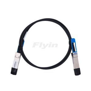

Description
Parameters
| Features | Application |
| Compatible with IEEE 802.3bj and IEEE 802.3cd. | Switches, servers and routers. |
| Wire AWG: AWG30, AWG24. | Storage area networks. |
| Optimized construction to minimize insertion loss and cross talk. | Data Center networks. |
| Straight and break out assembly configurations available. | High performance computing. |
| Customized cable braid termination limits EMI radiation. | Telecommunication and wireless infrastructure. |


Model | Rate | Interface | Sort | Cable Diameter | Transmission Distance |
FYDA-PP-**MB** | 10Gb/s | SFP+ to SFP+ | Passive | **AWG (24/30 Opt.) | 24AWG<10m,30AWG<3m |
FYAC-PP-**MB** | 10Gb/s | SFP+ to SFP+ | Active | **AWG (24/28/30 Opt.) | 24AWG<15m,28AWG<10m, 30AWG<3m |
FYDA-S28-**MB** | 25Gb/s | SFP28 to SFP28 | Passive | **AWG (26/28/30 Opt.) | 26AWG<5m, 28AWG<3m, 30AWG<3m |
FYDA-QQ-**MB** | 40Gb/s | QSFP+ to QSFP+ | Passive | **AWG (26/30 Opt.) | 26AWG<7m, 30AWG<3m |
FYDA-QP-**MB** | 40Gb/s | QSFP+ to SFP+ | Passive | **AWG (26/30 Opt.) | 26AWG<7m, 30AWG<3m |
FYDA-Q28-**MB** | 100Gb/s | QSFP28 to QSFP28 | Passive | **AWG (26/30 Opt.) | 26AWG<5m, 30AWG<3m |
FYDA-QS28-**MB** | 100Gb/s | SFP28 to SFP28 | Passive | **AWG (26/30 Opt.) | 26AWG<5m, 30AWG<3m |
FYDA-QQ56-**MB** | 200Gb/s | QSFP56 to QSFP56 | Passive | **AWG(26/30 Opt.) | 26AWG<3m, 30AWG<1.5m |
FYDA-QQ56-**MB** | 200Gb/s | QSFP56 to 2xQSFP56 | Passive | **AWG(26/30 Opt.) | 26AWG<3m, 30AWG<1.5m |
FYDA-QDD-**MB** | 400Gb/s | QSFP-DD to QSFP-DD | Passive | **AWG (28/30 Opt.) | 28AWG<3m, 30AWG<1.5m |
FYDA-QD256-**MB** | 400Gb/s | QSFP-DD to2* QSFP-DD | Passive | **AWG (28/30 Opt.) | 28AWG<3m, 30AWG<1.5m |
FYDA-OS456-**MB** | 400Gb/s | OSFP to 4*QSFP56 | Passive | **AWG (28/30 Opt.) | 28AWG<3m, 30AWG<1.5m |
FYDA-OOS-**MB** | 800Gb/s | OSFP to 2OSFP | Passive | **AWG(26/30 Opt.) | 26AWG<2m, 30AWG<1m |
FYDA-OOS-**MB** | 800Gb/s | OSFP to 4*QSFP112 | Passive | **AWG(26/30 Opt.) | 26AWG<2m, 30AWG<1m |
Remark: Above “**”refers to the corresponding meters. “**”refers to the optional cable diameter.

QSFP-DD passive copper cable assembly feature eight differential copper pairs,providing four data transmission channels at speeds up to 56Gbps(PAM4) per channel,and meets 400G Ethernet and InfiniBand Enhanced Data Rate(EDR) requirements.Available in a broad rang of wire gages-from 28AWG through 30AWG-this 400G copper cable assembly features low insertion loss and low cross talk. QSFP-DD uses PAM4 signals for transmission, which doubles the rate. However, there are more stringent requirements for cable insertion loss. For detailed requirements, please see High Speed Characteristics.
| Features | Application |
| Compatible with IEEE 802.3bj and IEEE 802.3cd. | Switches, servers and routers. |
| Wire AWG: AWG30, AWG24. | Storage area networks. |
| Optimized construction to minimize insertion loss and cross talk. | Data Center networks. |
| Straight and break out assembly configurations available. | High performance computing. |
| Customized cable braid termination limits EMI radiation. | Telecommunication and wireless infrastructure. |


Model | Rate | Interface | Sort | Cable Diameter | Transmission Distance |
FYDA-PP-**MB** | 10Gb/s | SFP+ to SFP+ | Passive | **AWG (24/30 Opt.) | 24AWG<10m,30AWG<3m |
FYAC-PP-**MB** | 10Gb/s | SFP+ to SFP+ | Active | **AWG (24/28/30 Opt.) | 24AWG<15m,28AWG<10m, 30AWG<3m |
FYDA-S28-**MB** | 25Gb/s | SFP28 to SFP28 | Passive | **AWG (26/28/30 Opt.) | 26AWG<5m, 28AWG<3m, 30AWG<3m |
FYDA-QQ-**MB** | 40Gb/s | QSFP+ to QSFP+ | Passive | **AWG (26/30 Opt.) | 26AWG<7m, 30AWG<3m |
FYDA-QP-**MB** | 40Gb/s | QSFP+ to SFP+ | Passive | **AWG (26/30 Opt.) | 26AWG<7m, 30AWG<3m |
FYDA-Q28-**MB** | 100Gb/s | QSFP28 to QSFP28 | Passive | **AWG (26/30 Opt.) | 26AWG<5m, 30AWG<3m |
FYDA-QS28-**MB** | 100Gb/s | SFP28 to SFP28 | Passive | **AWG (26/30 Opt.) | 26AWG<5m, 30AWG<3m |
FYDA-QQ56-**MB** | 200Gb/s | QSFP56 to QSFP56 | Passive | **AWG(26/30 Opt.) | 26AWG<3m, 30AWG<1.5m |
FYDA-QQ56-**MB** | 200Gb/s | QSFP56 to 2xQSFP56 | Passive | **AWG(26/30 Opt.) | 26AWG<3m, 30AWG<1.5m |
FYDA-QDD-**MB** | 400Gb/s | QSFP-DD to QSFP-DD | Passive | **AWG (28/30 Opt.) | 28AWG<3m, 30AWG<1.5m |
FYDA-QD256-**MB** | 400Gb/s | QSFP-DD to2* QSFP-DD | Passive | **AWG (28/30 Opt.) | 28AWG<3m, 30AWG<1.5m |
FYDA-OS456-**MB** | 400Gb/s | OSFP to 4*QSFP56 | Passive | **AWG (28/30 Opt.) | 28AWG<3m, 30AWG<1.5m |
FYDA-OOS-**MB** | 800Gb/s | OSFP to 2OSFP | Passive | **AWG(26/30 Opt.) | 26AWG<2m, 30AWG<1m |
FYDA-OOS-**MB** | 800Gb/s | OSFP to 4*QSFP112 | Passive | **AWG(26/30 Opt.) | 26AWG<2m, 30AWG<1m |
Remark: Above “**”refers to the corresponding meters. “**”refers to the optional cable diameter.
Company Info
Service Support
Sub-link
Add:Deliwei Industrial Park, Longhua, Shenzhen, China 518109
Tel:+86-755-29048607/85250091/32939610/32939620
Fax:+86-755-29048624
Email:sales@opticres.com
 EN
EN CN
CN

